19+ p&id diagram online
General Rules in Drawing of PIDs Pages. One pump will be operating while the other is idle.

Process Flow Diagrams Pfds And Process And Instrument Drawings P Ids Process Flow Process Flow Diagram Diagram
P-101AB indicates that the pump is located in area 100 of the plant.

. P-V diagram for water solid-liquid-vapor region If we heat ice at different vapor pressures and note down the corresponding change in volumes the saturation state points for solid liquid and vapor state from which a change of phase may occur without change of pressure and temperature for different pressures may be obtained on a p-V diagram. Support and structural details are also not included in p. IEEE Std 315-1975 Reaffirmed 1993 Graphic Symbols for Electrical and.
Mermaid lets you create diagrams and. PID Diagram - Online Drawing Tool. A PFD shows fewer details than a PID and is usually the first step in the design processmore of a birds eye view.
19 pid diagram online Rabu 02 Maret 2022 The best way to create a diagram is using libraries and templates that include all of the shapes styles and settings you need to assemble a particular type of drawing or diagram. It utilizes the graphic of MS-Visio and uses the object library of V-PID. Since PIDs are graphic representations of processes they have some inherent limitations.
Drawio can import vsdx Gliffy and Lucidchart files. The following topic sequence provides links. P-101AB indicates that this specific pump is number 01 in unit 100.
Its important to start with the correct standard as changing later will require remapping of your entire diagram. PID symbols exist for all major components and. They commonly include mechanical equipment ie.
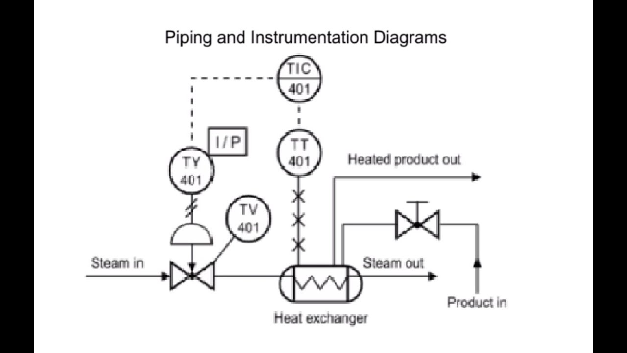
IP converter converts 4-20 mA electric signal into 3-15 PSI pneumatic signal PI converter converts 3-15 PSI pneumatic signal into 4-20 mA electric signal square-root extractor calculates the square root of an input signal. When you place components and lines in your PID drawings each component contains data that links to the Data Manager. Remove image background automatically in seconds.
PID symbols are a graphical representation of physical equipment that installed on the field. You can use it as a flowchart maker network diagram software to create UML online as an ER diagram tool to design database schema to build BPMN online as a circuit diagram maker and more. AutoCAD Plant 3D adds 3D models including piping equipment support structures generation of isometric and orthographic drawings.
PID and PFD Symbols. PID diagrams are simple to pick up and read. WHAT IS PID.
More fully developed piping and instrumentation diagrams PIDs are shown in a PID. Up to 9 cash back The Plant SDK provides development tools for both AutoCAD P ID and AutoCAD Plant 3D software. A very detailed diagram showing the processes happening within a plant the involved equipment and their interconnections.
There are few ISO and British standards available that provide symbols and best practices to draw PFD and PID such as ISA S51 BS 5070 and ISO 10628. Pipes expands when heated and contracts when cooled and the expansion can be expressed with the expansion equation. Capture your most cherished memories with our professional online photo book maker.
SmartDraw includes thousands of professionally designed symbols for architectural engineering mechanical electrical PID and HVAC drawings plus many more. Lets confirm this with the help of actual PID. P-101AB indicates that a backup pump is installed.
AutoCAD PID has four different symbol standards templates JIS ISA PIP ISODIN. AutoCAD P ID software allows you to create modify and manage schematic piping and instrumentation diagrams. How to Read the Process Flow Diagram PFD This is a PFD of the flushing oil system that shows the entire system of pump seal flushing oil.
Draw PID diagrams online in the browser with Google Docs. Anatomy of a PID Sheet Pages. PID diagrams depict the connection between piping equipment vessels and process.
The PID is the primary schematic drawing used for. Depending on your companys standards guidelines templates and region the one you use will vary. Thus there are two identical pumps P-101A and P-101B.
Valves vents flanges control inputs and outputs interfaces for class changes computer controlled systems and standardized. About Visio PID Process Designer V-PID V-PID Process Designer is a low cost offering from IT and Factory GmbH that assists in planning and design of the Process -flow and Piping Instrumentation diagrams your plant design. In the Data Manager you can view data reports export them to a spreadsheet or a comma separated values CSV file and import them back into the program.
El 99 de las empresas Fortune 500 confía en Lucidchart para mantener a sus equipos informados y. Within 10 minutes your email address may not be registered and you may need to create a new Wiley Online Library account. PID is the acronym for Piping and instrumentation diagram ie.
A set of standardized PID symbols is used by process engineers to draft such diagrams. Nuestra herramienta basada en la nube permite a los colaboradores trabajar juntos para un trabajo detallado y preciso. It is capable for more than 280 diagrams including Flowchart Network Diagram Org Chart Mind Map Floor Plan Project Chart Electrical Schematics PID UML Fashion Design Certificate and more.
Basic Difference EdrawMax is an all-in-one diagram software. Piping and Instrumentation Diagram Development. You can customize any of the existing built-in symbols or import your own symbols and save them for future use.
Pumps and Turbine PID Symbols. PIDs Piping Instrumentation Diagrams and PID Valve Symbol Library. An online form builder that has all the layout tools form fields and flexibility you need.
El software PID de Lucidchart es perfecto para dibujar tuberías y diagramas de instrumentación. Pipes and Tubes - Temperature Expansion. Engineering Symbology Prints Drawings Electronic Diagrams Schematics iv REFERENCES ASME Y145-2009 Dimensioning and Tolerancing.
This workflow describes how to design a PID drawing. PID is a schematic drawing that gives a primary visual representation of a process control system. A square root extraction of the input signal is applied as part of FIC 101s functionality.
What are the limitations of PID. Create flowchart UML ERD DFD ArchiMate BPMN floor plan wireframe PID and more. A piping and instrumentation diagram PID is a graphic representation of a process system that includes the piping vessels control valves instrumentation and other process components and equipment in the system.
Ok now you know what PID is and types of information youre going to get from the drawing. Referring to the Example PID diagram FT 101 represents a field-mounted flow transmitter connected via electrical signals dotted line to flow indicating controller FIC 101 located in a shared controldisplay device. Pumps compressors heat exchangers etc process piping sizes and identification control instrumentation and designation ie.
Flowchart Maker and Online Diagram Software. To as a converter and sometimes as a relay Examples. PID Drawings Use Cases.
Pipes - Fractional Equivalents. You can also add data to symbols and export a manifest. AutoCAD PID symbols standards.
It shows the essential details and information related to the conceptual design process with reality.

Plc Control System Control Systems Engineering Control Engineering Piping And Instrumentation Diagram
How To Read Piping And Instrumentation Diagram P Id Piping And Instrumentation Diagram P Id Diagram Diagram

Pin On Proccess 4 Practical

Piping And Instrumentation Documents Instrumentation Tools Piping And Instrumentation Diagram P Id Diagram Mechanical Engineering Design

Coriolis Piping And Instrumentation Diagram P Id Diagram Diagram

Piping And Instrumentation Documents Instrumentation Tools Piping And Instrumentation Diagram P Id Diagram Mechanical Engineering Design
P Id Flow System Example P Id Diagram Piping And Instrumentation Diagram Example

P Id Flow System Example P Id Diagram Piping And Instrumentation Diagram Example

P Id Guidelines For Centrifugal Compressor Systems Centrifugal Compressor P Id Diagram Compressor

How To Read Piping And Instrumentation Diagram P Id Piping And Instrumentation Diagram P Id Diagram Diagram

What Is A P Id Diagram In Laymen S Term Realpars P Id Diagram Diagram Piping And Instrumentation Diagram

Piping And Instrumentation Diagram P Id Software Piping And Instrumentation Diagram P Id Diagram Id Software

Determine Lrv And Urv Settings For The Level Transmitter Transmitter Electrical Wiring Diagram Chemical Engineering

Draw P Id Diagrams Online In The Browser With Google Docs P Id Diagram Diagram Online Drawing

Process Flow Diagrams Pfds And Process And Instrument Drawings P Ids Process Flow Diagram Process Flow Diagram